Monitoring system
Based on Internet of Things (IoT) technology, the system includes wireless sensors that measure oxygen levels regularly and transmit the data to a database.
The device is primarily designed to measure oxygen concentration in enclosed spaces where fluctuations in oxygen levels are anticipated, particularly in healthcare and industrial settings. The system consists of three main parts: wireless sensor modules, a communication gateway, which communicate with each other using hashtag IQRF® IoT technology utilizing a mesh network topology (IQMESH), and a superior system implemented on the University Server.
Authors: Jan Velicka, Martin Pies, Radovan Hajovsky, Katerina Barnova & Radek Martinek from VSB - Technical University of Ostrava

Oxygen concentration
Throughout the testing period, both oxygen concentration and temperature values were continuously recorded.
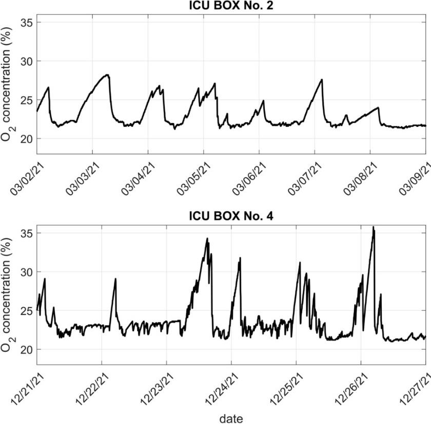
A weekly course of oxygen concentration in ICU Box No. 2 and ICU Box No. 4 from the peak period of the COVID-19 pandemic (March and December 2021), when highly specialised healthcare facilities were underhigh load, is shown in the picture.
As shown, there was an increase in oxygen concentration in the monitored areas during this period, up to a value of 30%. The hospital staff was alerted via a short message service and e-mail if the oxygen concentration threshold of 23.5% in the air was exceeded (with further alerts at 25% and 30%), and took the necessary measures to restore the safety of the given department. The overall accuracy of the monitoring system during the testing in real hospital conditions was ± 1%. The maximum measured oxygen concentration was 36%.

Energy consumption
The supply voltage of the node was set to 3.6 V, and the internal resistance of the SMU was set to 0 Ω. Specifically, this course uses markers to mark the area where the given module received the datapacket, processed the DPA request, activated the oxygen concentration measurement, and finally sent the databack to the coordinator. This entire sequence lasted for approximately tA = 991.5 ms, and the total average current drawn during this time was IA = 6.125 mA, which corresponded to an average power of PA = 22.05 mW.
When the RF part of the IQRF® module was asleep, the average current consumption was about 1.7 μ A. As soon as the RF part woke up, the consumption of the node increased to a value of 12 mA for approximately 1.2ms. This entire cycle took approximately tS = 48.9 ms. In this low-power mode, the average current consumption was approximately IS = 248.33 μ A, which corresponded to an average power of PS = 893.99 μ W.

Images